Garmin GI 275 Electronic Flight Instrument Receives EASA Approval
Our popular GI 275 electronic flight instrument has received European Union Aviation Safety Agency (EASA) approval, allowing installation in over 1,000 single-engine and multi-engine aircraft models. Several variants of the GI 275 are now available to meet the needs of business and general aviation aircraft. A powerful electronic flight instrument, the GI 275 is suitable as a direct replacement for a variety of legacy primary flight instruments in the cockpit such as the attitude indicator, attitude-direction indicator (ADI), course deviation indicator (CDI), horizontal situation indicator (HSI), multi-function display (MFD), and engine indication system (EIS). In addition, the GI 275 can also be installed as a standby attitude indicator when paired with large format electronic flight displays.
“Garmin worked closely with EASA to bring the popular GI 275 to thousands more cockpits with aging flight instruments,” said Carl Wolf, vice president of aviation sales and marketing. “With this approval, the modern GI 275 electronic flight instrument gives pilots the opportunity to take an economical and scalable approach to their avionics upgrade while realizing tremendous potential with the extraordinary capability of the versatile touchscreen GI 275.”
Lightweight and compact, the GI 275 is a reliable flight instrument intentionally designed to take advantage of the common 3.125-inch flight instrument size, reducing installation time and preserving the existing aircraft panel. Its bright, high-resolution touchscreen display and wide viewing angle offers superior readability in the cockpit. A dual concentric knob allows pilots to access a variety of key functions within the flight instrument, such as adjustments to the baro setting or the airspeed bug. Highly scalable, aircraft owners can start with a single GI 275 and add up to a total of six in a single panel, paving the way for incremental upgrades and an array of individualized panel configurations.
Primary and standby attitude indicator
When installed as a primary attitude indicator, the GI 275 offers improved reliability, potential weight savings and reduced maintenance compared to less reliable, vacuum-driven attitude indicators. When the GI 275 serves as primary for attitude information, pilots can also view altitude, airspeed and heading1 on the instrument. Optional Synthetic Vision Technology overlays a rich, 3D topographic view of terrain, traffic, obstacles, airport signposts and more, all within the GI 275 attitude display2.Additional features include the display of outside air temperature, groundspeed, as well as true airspeed and wind information on the attitude indicator.
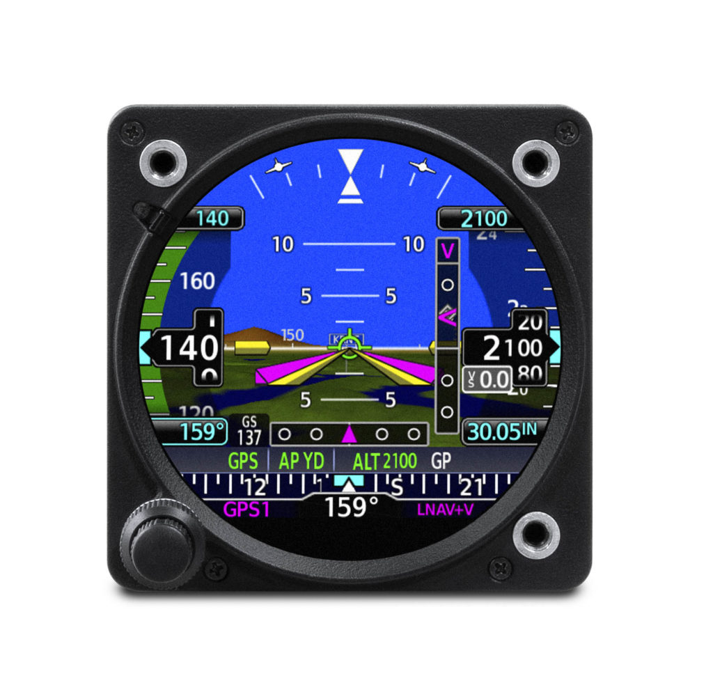
The GI 275 flight instrument is also approved for installation as a dedicated standby flight instrument to Garmin glass flight displays and is capable of serving as a back-up to a variety of third-party flight displays on the market. When installed as a standby flight instrument to the G500 TXi, the GI 275 is capable of displaying additional multifunction display features. In installations where the GI 275 is installed as a primary or standby flight instrument, a 60-minute back-up battery is included.
Course Deviation Indicator (CDI) & Horizontal Situation Indicator (HSI)
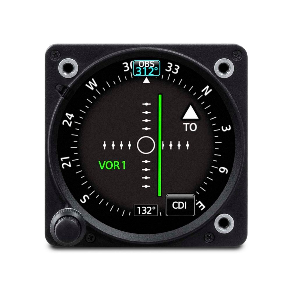
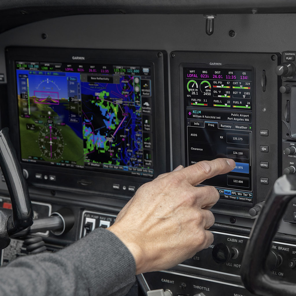
When installed as a CDI or HSI, the GI 275 is designed to accept a variety of GPS and navigation inputs, allowing up to two GPS sources and two VHF navigation sources. The GI 275 features an Omni Bearing Resolver that allows the flight instrument to interface to a variety of legacy navigators on the market without the need for an expensive adapter. With an optional magnetometer, it is also capable of providing magnetic-based HSI guidance. Selecting the CDI source is simple and can be accomplished through the touchscreen interface, while course and heading selection is completed using either the touchscreen or dual concentric knob. When aircraft owners replace an older mechanical CDI or HSI, the GI 275 doubles as a modern digital indicator and adds MFD-like capabilities such as a moving map, weather, traffic and terrain.
Autopilot compatibility with the GI 275
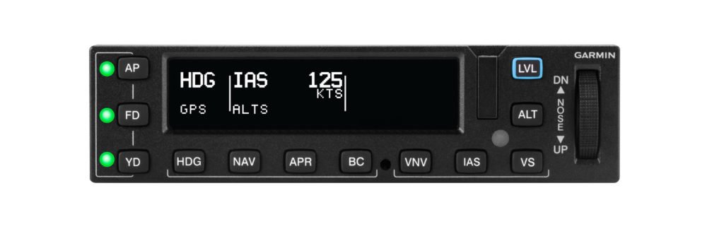
A single GI 2753 electronic flight instrument can be used as the attitude source to drive the GFC 500 autopilot, while also displaying mode annunciations and flight director indications. For added redundancy in aircraft equipped with a dual GI 275 installation, the secondary GI 2753 is capable of coupling to the GFC 500 autopilot, as well. In the unlikely event of a primary GI 275 failure, the autopilot remains fully functional when paired with the secondary GI 275. Additional redundancy is extended to include the G500 TXi & G600 TXi flight displays, which also allow the GI 275 to couple to the GFC 500 autopilot if needed when serving as a standby instrument. Unique to the GI 275 and TXi, pilots will receive a mis-compare annunciation if the AHRS sources between the two do not align. GI 275 is also compatible with the GFC 600 digital autopilot, as well as a variety of third-party autopilots and does not require a separate interface adapter, further reducing overall cost and installation labor. The GI 275 can replace the primary attitude indicator installed with these autopilots.
Additional capabilities
Depending on the configuration and installation, the GI 275 is capable of displaying additional page functions and features beyond a traditional flight instrument. These features can include:
- A multifunction display (MFD) with a moving map can display terrain, obstacles, traffic, weather, airspace information, airways, and more.
- When interfaced to a GTX 345 or GNX 375, traffic information can be displayed on the dedicated traffic page or moving map. Patented TargetTrend relative motion technology and pop-up traffic alerts further enhance situational awareness.
- The GI 275 can also be interfaced to a variety of traffic systems, including select Traffic Advisory (TAS) and Traffic Alert and Collision Avoidance Systems (TCAS). Traffic advisories are displayed on the dedicated traffic page and moving map.
- SafeTaxi airport diagrams display runways, taxiways, Fixed Based Operators (FBO’s), hangars and more relative to the aircraft’s location on the airport surface.
- Terrain shading incorporates yellow and red contouring depicting the aircraft is 1,000 and 100 feet above ground level (AGL) respectively. Terrain and obstacle information can be viewed on the terrain and map pages.
- The GI 275 uses its internal terrain and obstacle database to provide audible and visual terrain proximity alerts, including, “terrain ahead, pull up” and “obstacle ahead, pull up.”
- Engine information system with optional interface module and GEA 110 sensor has the ability to serve as a primary EIS display for piston engine, fuel, electrical and other data. Dual GI 275 flight instrument installations are able to display engine information for twin-engine aircraft.
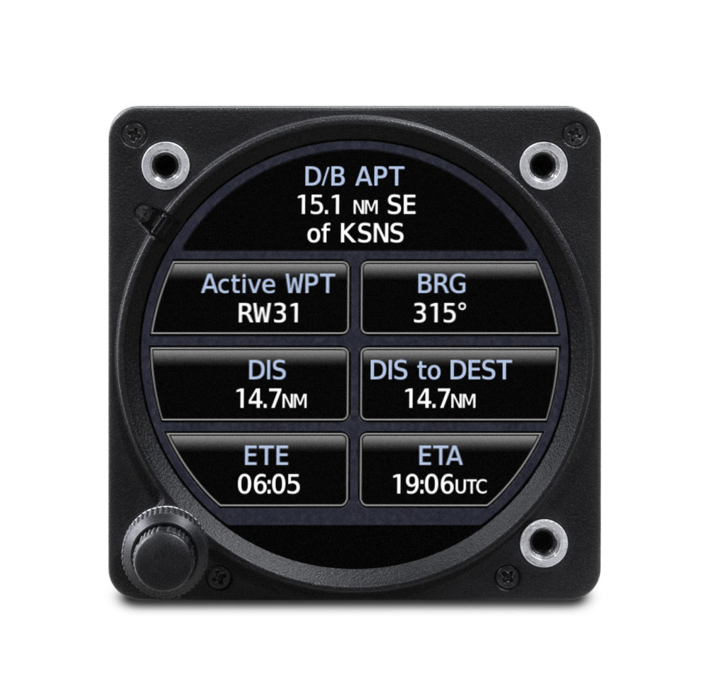
- An airport information page displays a variety of data, including frequencies, runway dimensions and more.
- The GI 275 can be paired with the GRA 55/5500 and other third-party products to display radar altimeter on a dedicated page. Visual and aural annunciations are also available.
Built-in Wi-Fi enables Garmin’s Database Concierge, the wireless transfer of aviation databases to the GI 275. Pilots also have the option of transferring databases to the GI 275 using a USB flash drive and the GSB 15 USB charger. Databases can also be synced among multiple GI 275 flight instruments in a single cockpit. When configured to display engine information, the GI 275 can wirelessly send engine data to display within the Garmin Pilot app on Apple mobile devices. This data is also automatically synced and can also be viewed and stored on the flyGarmin website. Wireless flight plan transfer via Bluetooth is available when the GI 275 is paired with a GPS 175, GNC 355 or GNX 375. Additional wireless functions include the sharing of GPS position and back-up attitude information with Garmin Pilot.
The GI 275 is available immediately and approved for installation in over 1,000 single-engine and multi-engine aircraft models. Select Class IV aircraft also are approved; visit www.garmin.com/GI275 for additional information. For full installation details, and to purchase the GI 275, contact a Garmin Authorized Dealer. A trial period of SVT also comes with the purchase of a GI 275 when it’s configured as an attitude indicator. The GI 275 also comes with a two-year warranty and is supported by our award-winning aviation support team, which provides 24/7 worldwide technical and warranty support. For the 17th consecutive year, both Aviation International News and Professional Pilot magazine, two predominant aviation publications, awarded the Garmin aviation support team top honors for avionics product support. For additional information, visit www.garmin.com/aviation.
- Requires an optional magnetometer
- Features and functions depend on configuration and variant selected, visit a Garmin Authorized Dealer for additional information.
- Requires GI 275 ADAHRS variant.
The post Garmin GI 275 Electronic Flight Instrument Receives EASA Approval appeared first on Garmin Blog.
https://www.garmin.com/en-US/blog/aviation/garmin-gi-275-electronic-flight-instrument-receives-easa-approval/
Garmin GFC 600 Digital Autopilot Approved for Select King Air C90 and E90 Aircraft
Our GFC 600 digital autopilot has received FAA STC approval in select Beechcraft King Air C90 aircraft and E90 aircraft1. GFC 600 is optimized for turbine aircraft, delivering superior in-flight characteristics and new operational capabilities such as Vertical Navigation (VNAV), automatic Course Deviation Indicator (CDI) switching when paired with a GTN Series navigator, enhanced go-around capability and much more.
The GFC 600 certification for the Beechcraft King Air C90 and E90 provides owners and operators an autopilot upgrade that boasts superior integration potential with G600 and G600 TXi flight displays, the GI 275 electronic flight instrument, as well as the GTN and GTN Xi Series of navigators. The self-contained autopilot controller incorporates backlit keys and a bright, sunlight readable display that depicts autopilot status and mode selection. An intuitive built-in control wheel also provides convenient adjustment of aircraft pitch, airspeed and vertical speed modes. When the level button is selected, the aircraft automatically returns to straight-and-level flight.
Environmentally hardened autopilot servos designed for harsh operating conditions contain brushless DC motors offering improved performance and reducing maintenance requirements when compared to decades-old servo designs on the market today. In addition, these servos are optimized for turbine aircraft by offering more torque to help better command and respond to control demands required of turbine aircraft.
Standard mark-width design of the GFC 600 mode controller ensures the autopilot controller allows for routine installation into the aircraft’s avionics stack. Autopilot mode annunciation is available on the G600 TXi touchscreen glass flight display, as well as the G600 flight display. The addition of an optional autopilot annunciator panel also displays the selected autopilot mode in the pilot’s primary field of view and retains an identical footprint of third-party autopilot annunciators on the market.
In addition to traditional autopilot capabilities such as altitude hold, vertical speed and heading modes, the GFC 600 also includes:
- Premium functions and advanced capabilities such as altitude pre-select2 and indicated airspeed hold mode
- Pilots can select, couple and fly various instrument approaches, including GPS, ILS, VOR, LOC and back course approaches3
- Built-in GPS roll steering capability eliminates the need for external roll steering converters, allowing for smoother navigation tracking when installed with a compatible navigator
- Level Mode button, which automatically engages the autopilot to restore the aircraft to straight and level flight
- Underspeed protection helps prevent the pilot from stalling the aircraft
- Overspeed protection helps prevent the pilot from exceeding aircraft maximum speed (VNE)
- Yaw Damping (YD) mode minimizes yawing oscillations while also helping to maintain coordinated flight
- Flight Director command bars can be displayed on flight display such as the G600 and G600 TXi
- Pilots can fly coupled ‘go-arounds’ during missed approach sequencing. A remotely-installed go-around button commands the Flight Director to display the appropriate pitch attitude required for the missed approach procedure and activates a loaded missed approach when paired with a GTN 650/750 or GTN 650Xi/750Xi navigator
- Included pitch-trim servo adds automatic trim and improved manual electric trim
- Control wheel steering is available, which allows the pilot to adjust pitch, roll, altitude hold, vertical speed or airspeed references using the control yoke while the autopilot is engaged
As a standard feature, pilots receive Garmin ESP with the GFC 600 autopilot, which works to assist the pilot in maintaining the aircraft in a stable flight condition. ESP functions independently of the autopilot and works in the background to help pilots avoid inadvertent flight attitudes or bank angles and provide airspeed protection while the pilot is hand-flying the aircraft.
The GFC 600 digital autopilot for the Beechcraft King Air C90/E90 is available immediately through select Garmin authorized dealers. To view the most up-to-date aircraft STC list, to view certifications that are expected to begin in the next 12-months, or to express interest in a specific aircraft make/model for the GFC 600, visit www.garmin.com/GFC600. For additional information, visit: www.garmin.com/aviation.
1. STC approved for Beechcraft King Air C90, C90-1, C90A, C90B, C90SE, C90GT, C90GTi, E90, and does not include those aircraft equipped with Garmin G1000/G1000 NXi, or Collins Pro Line integrated flight decks.
2. Available on GFC 600 or Garmin flight displays.
3. GFC 600 requires an external navigator for navigation and approach functions. See website for additional compatibility information.
The post Garmin GFC 600 Digital Autopilot Approved for Select King Air C90 and E90 Aircraft appeared first on Garmin Blog.
https://www.garmin.com/en-US/blog/aviation/garmin-gfc-600-digital-autopilot-approved-for-select-king-air-c90-and-e90-aircraft/
Appareo Releases New Open Platform Telematics Device with Truly Global Connectivity
NEWS RELEASE
Appareo Releases New Open Platform Telematics Device with Truly Global Connectivity
The IP67-rated Gateway 370 features Iridium® SBD, 4G/3G/2G, and eSIM, certified for use in the USA, Canada, Europe, Brazil, and more.
FARGO, North Dakota (January 21, 2021) — Appareo today released a new product in the company’s award-winning line of telematic control units (TCUs). The Gateway 370 is a rugged yet lightweight edge computing platform for mobile equipment applications that provides a wide range of communication technologies. This release builds on the Gateway 270 model that was launched in 2020, adding an Iridium short burst data (SBD) satellite transceiver for truly global communication capabilities, and a 433 MHz receiver for use with sensors and active RFID tags.
Gateway 370 is built on an open and flexible platform that supports standard programming languages and tools, allowing Appareo customers to quickly and easily develop their own applications on the hardware. The device is built on a popular distribution of embedded Linux (Yocto) with Docker support, allowing a convenient development environment for C++, C#, or other common development languages.
“This flexibility and approachability gives Appareo customers the control they desire — allowing them to use a variety of approaches and resources to achieve the maintenance, service, and operational benefits customized to their needs,” said David Batcheller, President & CBO of Appareo.
In addition to the satellite and 433 MHz radios, the Gateway 370 comes with the full set of features found in the Gateway 270 model, including global LTE CAT 4 cellular radio with 3G/2G fallback and eSIM; dual core processor for handling significant computational capabilities at the edge; Wi-Fi and Bluetooth interfaces for communication between mobile devices and the machine for control and/or monitoring purposes; 6x CAN bus interfaces; Ethernet; BroadR-Reach; RS-232; GPS; and more.
These capabilities are housed in an IP67-rated rugged enclosure for use outdoors and for mounting on construction and agricultural machinery. The device’s array of wired and wireless communication technologies make it well suited for a broad spectrum of equipment control, monitoring, and connectivity challenges.
Wide Area Network
The Gateway 370 is certified for deployment in a broad range of North American, South American, and European markets, making it ideal for equipment manufacturers with broad geographic distribution. Appareo worked with carrier partners Vodafone International and Tata Communications to maximize the geographic potential of the Gateway 370. However, cellular coverage is still limited in some geographies. Appareo’s inclusion of an Iridium transceiver in Gateway 370 ensures that Appareo customers stay connected with their machines and that critical machine data can be retrieved, wherever that equipment may be (land, air, or water).
Local Area Network
The LAN connections (Wi-Fi, Bluetooth, and 433 MHz) allow machines to communicate directly with each other and with the operators or passengers. For example, people near the machine can be connected, informed, or in control, using real-time data with zero latency and no network costs. Further, the Gateway 370 can communicate with active RFID products (e.g., asset trackers), tire pressure sensors, and other wireless machine sensors. This capability allows for machines to receive information from hydraulic and mechanical attachments, and despite the lack of electrical power on those attachments, use information from the active RFID tag to recognize the attachment, and automatically adjust machine control settings accordingly.
For applications where Iridium is not required and the application may be more cost sensitive, defeatured variants of the Gateway telematic control units are available with the same open platform principle. This family design approach allows Appareo customers to access and utilize a variety of TCUs, on the same open platform, with a variety of capabilities and price points to address specific needs.
Appareo Gateway Series
To contact Appareo, acquire a development kit, and begin working with Appareo Gateways, visit appareo.com/gateways.
# # #
About Appareo
Appareo is a recognized leader in the custom design, development and manufacture of innovative electronic and software solutions for aerospace and terrestrial applications. Through the creative application of cutting-edge technologies, Appareo creates complex end-to-end solutions that include both mobile and cloud-based components. The company is privately held, with headquarters in Fargo, N.D., and a design office in Paris, France. All products are built and supported in the USA.
Product Photos: appareo.com/media
https://www.appareo.com/2021/01/21/appareo-releases-new-open-platform-telematics-device-with-truly-global-connectivity/
Airbus Helicopters Honors Garmin with Consecutive On-Time Delivery Awards
Airbus Helicopters, Inc. honored the Garmin aviation team with a 2020 On-Time Delivery Award from Airbus Helicopters, Inc. for its efficient performance related to product delivery. Garmin avionics are available as standard on select Airbus Helicopters, including the H125, H130, H135 and H145.
Each year, Airbus Helicopters, Inc. recognizes suppliers who stand out in performance, competitiveness and reliability. This is the second year in a row Garmin has won the On-Time Delivery Award for commitment and timeliness in delivering avionics to fulfill Airbus Helicopters Inc. production lines and customer orders.
“We are once again very proud to be recognized by Airbus with this prestigious award for our commitment to serve them and our mutual customers with the on-time delivery of our products,” said Carl Wolf, Garmin vice president aviation sales and marketing. “To again receive this award is truly humbling and ultimately would not be possible without the dedication of our entire Garmin team, in addition to the gratifying strategic relationship with Airbus Helicopters.”

Garmin avionics are available as standard on the Airbus H125, including the G500H TXi flight display, GTN 650 touchscreen navigator, GNC 255 nav/comm, GMA 350c audio panel and the GTX 335R remote-mount ADS-B Out transponder. The GTN 750, GNC 255 and GTX 335R are also available as standard on the H130, while the H135/H145 feature the GTN 750 and Flight Stream 510 as standard equipment.
This marks the third consecutive year Garmin has received an award from Airbus Helicopters, Inc. In 2018, Garmin was also recognized by Airbus Helicopters, Inc. as the Supplier of Excellence for its unmatched responsiveness and competitiveness in its support of the UH-72A Lakota helicopter program, and for its overall support at the Airbus Helicopters Inc. finally assembly and completion center in Columbus, Miss.
The post Airbus Helicopters Honors Garmin with Consecutive On-Time Delivery Awards appeared first on Garmin Blog.
https://www.garmin.com/en-US/blog/aviation/airbus-helicopters-honors-garmin-with-consecutive-on-time-delivery-awards/
Garmin Receives Consecutive Supplier of the Year Awards from Embraer
Embraer awarded the Garmin aviation team with its 11th Supplier of the Year award in the past 10 years. The Supplier of the Year distinction was presented in the Electric and Electronic Systems category for the G3000® Prodigy Touch flight deck systems in the Phenom 100EV and Phenom 300E.
“We are honored to receive consecutive Supplier of the Year awards from Embraer,” said Carl Wolf, Garmin vice president of aviation sales and marketing. “These honors go beyond the product; they represent the strong collaboration between Garmin and Embraer resulting in a terrific in-flight experience for our mutual customers. It is truly rewarding and motivating for our employees to receive eleven Supplier of the Year awards over the ten-year period”
Embraer recognized a select group of elite suppliers for their outstanding performance in various categories. The 2019 Electric and Electronic Systems award recognizes design innovation, ease of use and overall system architecture, as well outstanding efforts in production line support, quality and on-time reliability of the supply chain. This award also distinguishes our commitment to design and manufacture state-of-the-art flight deck systems, while being responsive to market needs and preferences.
This is the 11th supplier award presented to Garmin by Embraer.
- 2019: Electric & Electronic Systems
- 2018: Electric & Electronic Systems
- 2017: Technical Support to Operator
- 2017: Electro – Electronic Systems
- 2016: Electro – Mechanical Systems
- 2015: Electro – Mechanical Systems
- 2015: Material Support to Operator
- 2014: Material Support to Operator
- 2011: Electro – Electronic Systems
- 2011: Technical Support to Operator
- 2010: Electro – Electronic Systems
Among hundreds of suppliers, best supplier recipients undergo stringent evaluation and are recognized as having shown outstanding performance, continuous improvement and increased customer satisfaction among all other suppliers in their respective categories. Nine award categories were presented among Embraer’s entire aircraft portfolio, including Executive Aviation, Defense, and Commercial Aircraft. Suppliers are considered based on several attributes, including innovation, delivery, quality, reliability, flexibility and customer support.
The post Garmin Receives Consecutive Supplier of the Year Awards from Embraer appeared first on Garmin Blog.
https://www.garmin.com/en-US/blog/aviation/garmin-receives-consecutive-supplier-of-the-year-awards-from-embraer/
TXi Touchpoint: Not Your Average HSI
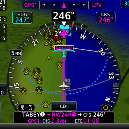
The horizontal situation indicator (HSI) commands a significant portion of a pilot’s attention throughout a flight, especially during instrument procedures. Your focus and attention are balanced between various instruments, processing information and deciphering data as you make decisions in the cockpit. A primary flight display that can concentrate this critical information within pilots’ primary field of view could help reduce workload and streamline actions during these critical phases of flight. We took this into consideration with our TXi flight display series and developed an HSI mapping feature that provides not only traditional heading information and course guidance, but also additional data overlays to enhance pilots’ situational awareness. This touch-interface, MFD-like map can present NEXRAD imagery and weather, as well as SafeTaxi® diagrams, traffic, terrain alerting and more.
Better understand the weather around you
The TXi HSI map can overlay SiriusXM® Aviation Satellite Weather, ADS-B datalink weather or Doppler Radar, providing a better understanding of conditions and how they relate to your current position. For an added layer of weather information, Stormscope®, cell data and lightning strike information also can be viewed within the HSI map. Plus, it’s easy to zoom in for a closer look or zoom out for a ”higher-level” view of the conditions, simply swipe your finger up and down on the touchscreen HSI display.
ADS-B traffic targets
Also, keep an eye on surrounding ADS-B-equipped traffic. On aircraft properly equipped with select ADS-B solutions and a TXi series flight display, this dual-link position tracking feature allows you to see where an aircraft target is with respect to your own aircraft’s position within the HSI map. If a target gets too close, it changes to a highlighted yellow icon for added awareness.
Terrain alerting
Hazardous terrain up ahead? The TXi HSI map presents the surrounding landscape in shades of green, yellow and red — from lowest risk to highest risk, respectively. If you’re approaching dangerous terrain, an alert will indicate the close proximity, helping the aircraft remain clear of hazards and on course.
Obstacles awareness
Stay apprised of obstacles along your flight path, like towers and buildings, while staying on course. Like terrain alerting, obstacles are displayed by degree of hazard — white indicating “no factor,” yellow to “be cautious” and red representing “danger.” As you approach dangerous obstacles, the indications become more distinct and pronounced, alerting pilots to take corrective action if necessary.
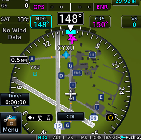
SafeTaxi airport navigation
We created SafeTaxi to help pilots navigate airports more easily. This tool displays a geo-referenced airport diagram and displays runways, taxiways and hangars relative to an aircraft’s location on the field. It also identifies hold short lines, providing pilots an even greater level of awareness to their location within the terminal environment.
WireAware and HTAWS for Helicopters
Helicopter pilots can benefit from the TXi HSI map too. Our G500H TXi for helicopters combines our WireAware wire-strike avoidance technology with optional HTAWS (Helicopter Terrain Awareness and Warning System) data to provide a comprehensive solution. It can help identify dangerous terrain and hazardous obstacle transmission (HOT) lines for the U.S. as well as some locations in Canada and Mexico.
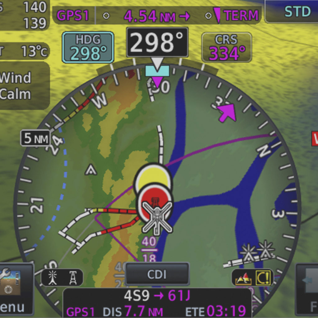
In addition to TXi series flight displays, select HSI mapping features and functions are available with G1000® NXi, G3000® and G5000® integrated flight decks, as well as our GI 275 electronic flight instrument. To learn more about our HSI map, and all of our safety-enhancing aviation solutions, visit Garmin.com/aviation.
Sirius, XM and all related marks and logos are trademarks of Sirius XM Radio Inc.
Stormscope is a registered trademark of L-3 Communications.
The post TXi Touchpoint: Not Your Average HSI appeared first on Garmin Blog.
https://www.garmin.com/en-US/blog/aviation/txi-touchpoint-not-your-average-hsi/
More Effectively Manage Engines, Fuel with Garmin Engine Indication System
The benefits of digital engine indication systems (EIS) go far beyond replacing an aging system in your aircraft. These modern, reliable solutions can offer significant improvements over older, maintenance-prone analog instruments. They also can present crucial engine and fuel information with enhanced precision. Streamlined displays with intuitive user interfaces can help reduce pilot workload, improve engine and fuel management, and add overall confidence in the cockpit. Our broad range of EIS solutions were designed with these principles in mind. From our compact GI 275 EIS to our larger format EIS TXi and G3X Touch , we have an EIS solution for nearly every aircraft type and operator budget.
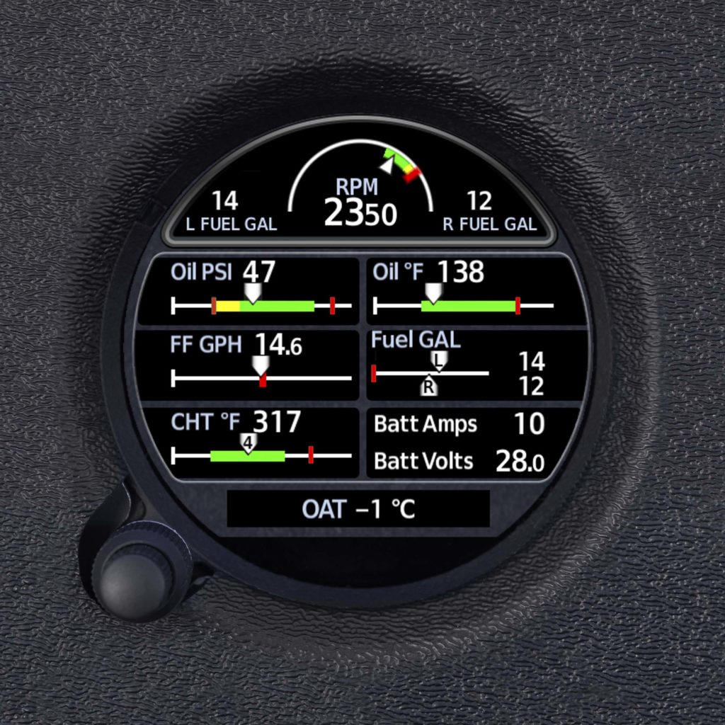
GI 275 EIS: Convenient size, powerful capabilities
Don’t be fooled by the size of our GI 275 EIS. Designed to fit a standard 3-1/8” instrument cutout, this stand-alone touchscreen solution provides engine, fuel, electrical information and more in a convenient, cost-effective package. Plus, with minimal or no panel modifications required for installation, GI 275 proves ideal for aircraft owners looking to keep the classic look of their panel. It graphically displays cylinder head and exhaust gas temperatures, features lean assist mode, and monitors fuel quantity and fuel flow to estimate how much fuel, range and flight time remains.
EIS TXi: Larger display, broader aircraft applicability
Looking for more display real estate to monitor engines and fuel? Our dedicated EIS TXi presents the same essential engine, fuel and electrical information as the GI 275 EIS but with a few more features on a larger touchscreen format – available in 7” landscape or 7” portrait options. It’s available for most normally aspirated or turbocharged Lycoming/Continental 4- to 6-cylinder singles and twins, as well as select single engine turboprop aircraft.
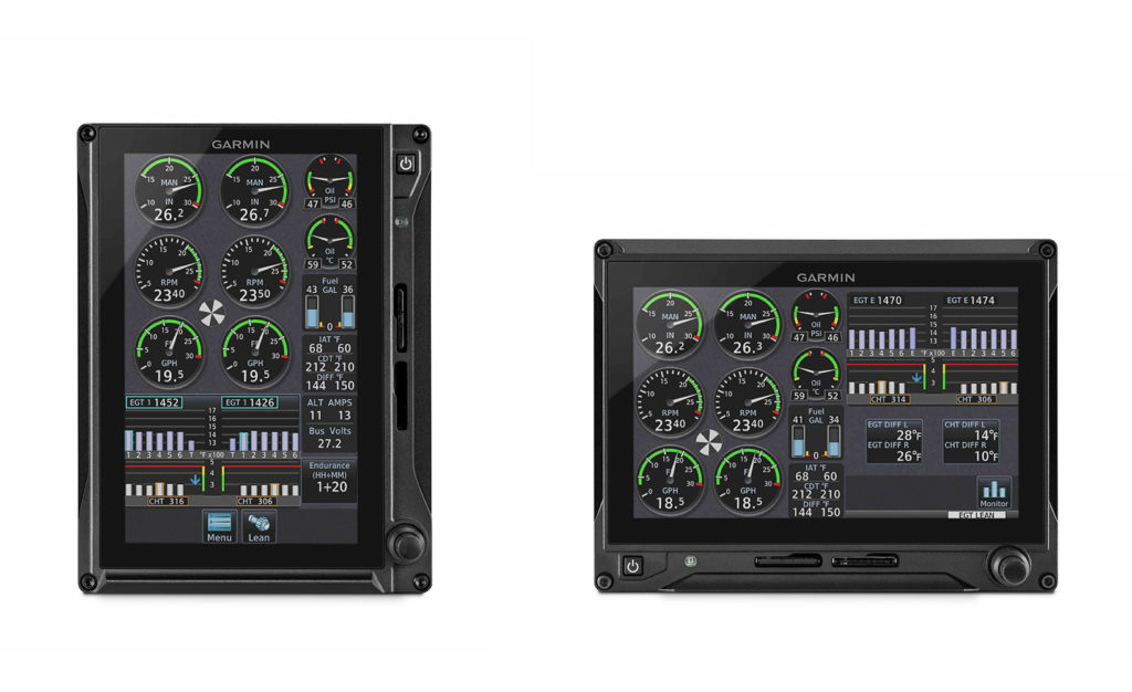
For turboprop operators, EIS TXi can display dynamic gauge range markings for torque, prop RPM, Ng percent, interstage turbine temperature and more. Automatic, color-coded data bands based on the aircraft’s current condition will illuminate, with automatic timers and exceedance warnings prompting visual cues to flash, highlighting each out-of-limit parameter.
Integrate EIS with PFD, MFD on G500/G600 TXi, G3X Touch
Some pilots prefer a panel layout with more integration and fewer displays. Our G500/G600 TXi and G3X Touch flight displays can combine EIS information with PFD and MFD capabilities in several sizes and configurations, providing an “all-in-one” flight display solution.
For panel upgrades with space for more than one display, both the TXi and G3X Touch series offer a stand-alone EIS/MFD combination. In this layout, available for single-engine piston aircraft, the EIS indications can be viewed in either an expanded format or a condensed strip on the touchscreen, allowing pilots to view MFD information next to the engine information. The opportunities TXi and G3X Touch offer to integrate allow expanded flexibility and functionality in individual displays.
Customizable exceedance alerting and engine performance data logging
Predefined and pilot-selectable exceedance alerting comes standard with GI 275 EIS, EIS-capable TXi and G3X Touch flight displays. During installation, predefined limits are set for engine temperatures, oil pressure and more. After the install is completed, pilot-selectable alerts can be configured by operators to provide an extra level of protection. These pilot-selectable alerts are intended to signal the pilot before an exceedance is reached. Both predefined and pilot-selectable alerts prompt flashing cues, helping to identify potential out-of-limit exceedances and maintain long-term engine performance and overall health.
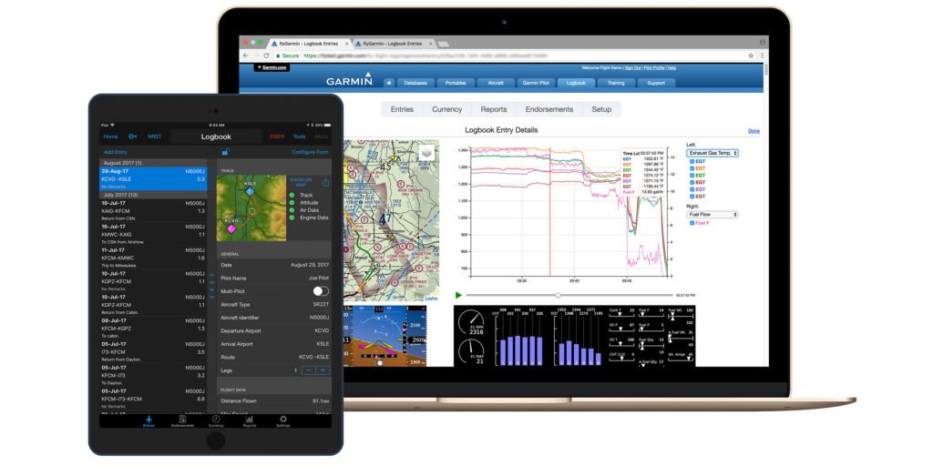
These EIS solutions can automatically log engine performance data for post-flight analysis. With the EIS-capable GI 275, data is automatically logged within the instrument, then can be wirelessly transmitted to a compatible mobile device downloaded with the Garmin Pilot app. Our G3X Touch displays log data to an SD card installed in the display, which can be manually uploaded to flyGarmin.com or wirelessly transmitted to Garmin Pilot. EIS-equipped TXi displays automatically log engine data within the display too, and a Flight Stream 510 (sold separately) can wirelessly transmit EIS data to Garmin Pilot. In fact, engine performance data can be wirelessly transmitted to and displayed on Garmin Pilot in-flight. After landing, and engine data is transmitted to Garmin Pilot, it is automatically uploaded to flyGarmin.com and available for post-flight review. All information in flyGarmin.com is stored securely within our web-based cloud service.
To learn more about all of our EIS solutions and latest avionics, visit Garmin.com/aviation.
The post More Effectively Manage Engines, Fuel with Garmin Engine Indication System appeared first on Garmin Blog.
https://www.garmin.com/en-US/blog/aviation/more-effectively-manage-engines-fuel-with-garmin-engine-indication-system/
New FltPlan.com AeroData Runway Analysis Service for Business Aviation Operators
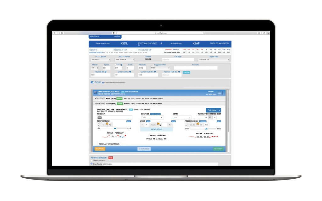
Our FltPlan.com platform now features a new integrated runway analysis service from AeroData, allowing pilots to calculate performance data while creating a flight plan through FltPlan.com. AeroData runway analysis joins Aircraft Performance Group (APG) and Automated Systems in Aircraft Performance (ASAP) runway analysis services available from FltPlan.com. All three of these runway analysis offerings through FltPlan.com eliminate the need for pilots to reference manuals and perform their own manual calculations for takeoff and landing data, ultimately resulting in time savings and more accurate performance numbers. The tailored performance data allows crews to maximize the performance of the aircraft while also assuring compliance with runway and obstacle requirements. Additional features of the AeroData service include concise engine- out escape procedures that factor in obstacles and terrain, the ability to specifically configure Takeoff- and-Landing Data (TOLD) based on conditions and limitations, automatically calculate aircraft fuel requirements based on the flight plan, integration with Garmin PilotTM and much more.
“AeroData is the premier runway analysis provider for commercial air carriers in North America and Garmin is excited to integrate this service with FltPlan.com for use by our business aviation customers,” said Carl Wolf, Garmin vice president of aviation sales and marketing. “Pilots and operators now have the unique ability to calculate performance data and receive obstacle clearance while creating their flight plan on FltPlan.com – maximizing aircraft performance for the intended operation.”
AeroData expands into business aviation
As one of the leading providers of runway analysis for commercial airlines, AeroData serves over 135 airlines globally and is the data provider for more than 70 percent of airline flights in North America. The integration with FltPlan.com brings AeroData, an experienced data provider, into business aviation, giving pilots the ability to include information and calculations directly in the flight planning stage, saving valuable time and helping to increase accuracy. The more accurate performance data allows operators to optimize loading based on the consideration of airfield and aircraft conditions and provides an engine failure procedure (EFP) based on a detailed analysis of obstacles and terrain in the airport environment.
TOLD calculations
FltPlan.com’s flight planning engine automatically selects a preferred runway and aircraft configuration based on current aircraft and airfield conditions, which include the use of the current METAR, or forecast for the time of departure. Further, crews can tailor additional configurations that include runway direction; surface contaminant; runway length; weather information such as winds, temperature, and altimeter setting; aircraft flap configuration; and Minimum Equipment List (MEL) penalties. Additionally, when an aircraft is performance limited by factors such as runway condition or climb gradient requirements, crews can adjust aircraft and airfield configurations to calculate performance numbers that would help maximize aircraft operation. Applicable NOTAM information is also actively monitored and is reflected in TOLD calculations.
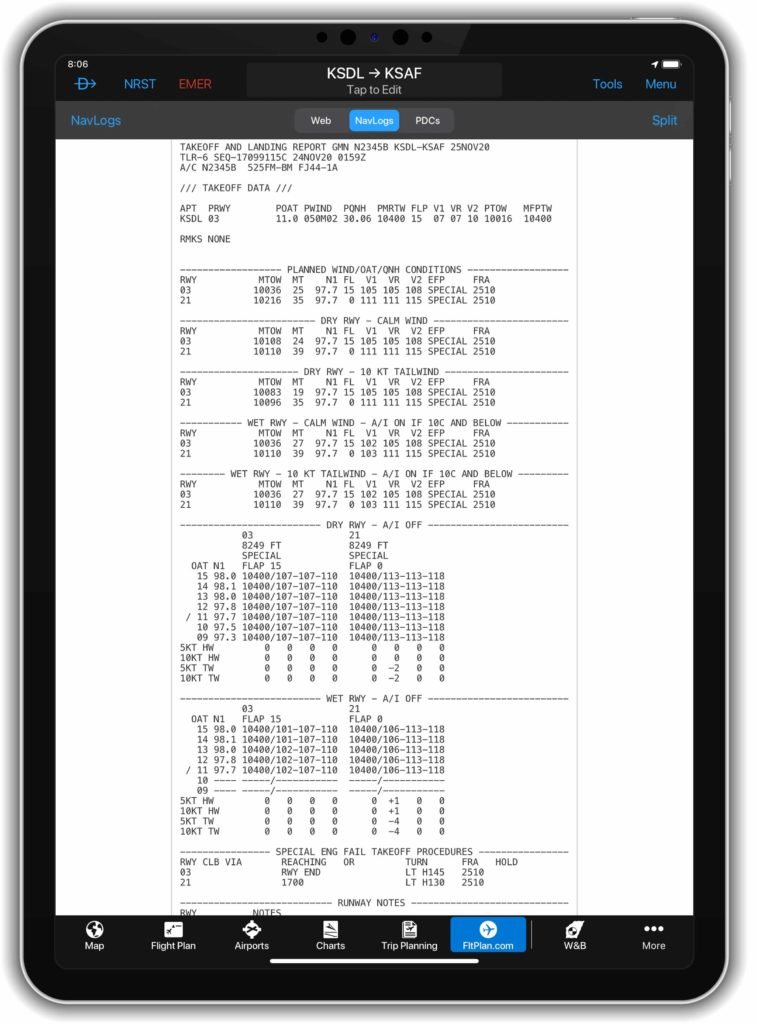
Performance calculations automatically added to FltPlan.com NavLog
After TOLD calculations are complete, a Takeoff and Landing Report (TLR) is generated and added to the FltPlan.com NavLog for reference. The TLR displays comprehensive data such as takeoff reference speeds, flap settings, power settings, environmental control system (ECS), anti-ice settings, runway surface conditions including contaminant level, tailwind calculations, and Maximum Runway Takeoff Weight (MRTW) for each available runway on the airfield. To better understand factors driving performance, crews can review limiting factors on the TLR that include climb performance, field length, or obstacle clearance, to name a few.
Easily accessible in-flight through the NavLog, landing performance data is included on the TLR based on calculated enroute fuel burn. Landing data shows reference speed (VREF) and landing distance based on landing weight, flap settings, ECS and anti-ice configurations, as well as reported braking action. Both factored and unfactored landing distances are displayed as separate options.
Additionally, pilots have the ability to easily view the TLR on a portable electronic device within the Garmin Pilot and FltPlan Go apps. This integration appends the TLR to the FltPlan.com NavLog for a quick and convenient way to reference runway analysis information while in flight.
Fuel order information is also automatically generated when creating a flight plan. This convenient feature assists pilots in that they no longer have to manually calculate the required fuel load while the system also checks basic structural weight limits of the aircraft to ensure that limitations will not be exceeded.
Engine Failure Procedures included in TLR
The TLR also uses calculated data to specify engine failure procedures (EFP) for each runway and aircraft configuration. When standard EFP’s cannot be used due to obstacle requirements, special procedures are calculated and provided on the TLR. Where terrain and obstacles limit straight out climb, AeroData designed EFP’s provide clear and concise guidance for pilots to perform a safe escape maneuver in a high workload flight environment.
AeroData Runway Analysis is available in two service options with one providing runway analysis, and another providing runway analysis plus obstacle clearance considerations. For more information on AeroData and runway analysis services, and to view supported aircraft, please visit www.FltPlan.com/Runway.htm.
The post New FltPlan.com AeroData Runway Analysis Service for Business Aviation Operators appeared first on Garmin Blog.
https://www.garmin.com/en-US/blog/aviation/new-fltplan-com-aerodata-runway-analysis-service-for-business-aviation-operators/
Smart Rudder Bias: Safety-Enhancing Technology for Select Twin-Engine Piston Aircraft
Our GFCTM 600 digital autopilot has been upgraded to feature new safety-enhancing capabilities, including Smart Rudder Bias for select piston twin-engine aircraft. Part of our AutonomiTM family of automated flight technologies, Smart Rudder Bias provides additional assistance against hazardous effects of a one-engine inoperative (OEI) event when appropriately equipped. It also provides pilots assistance in maintaining control of the aircraft while determining the next course of action, simultaneously reducing workload in a high-stress and time-critical flight environment.
“We are proud to be able to offer a new safety tool for twin-engine piston aircraft with the introduction of Smart Rudder Bias, making the GFC 600 digital autopilot the most advanced solution for this class of aircraft on the market today” said Carl Wolf, Garmin vice president of aviation sales and marketing. “With the introduction of Smart Rudder Bias technology, working together with the other Garmin systems onboard, pilots can react to an engine failure by quickly and accurately detecting the issue while simultaneously receiving automatic assistance applying the correct flight control input – providing an additional safety tool not seen before in twin-engine piston aircraft.”

Help manage aerodynamic performance with Smart Rudder Bias
Twin-engine aircraft inherently have aircraft controllability concerns in the event of an engine failure and pilots can expect a significant yaw toward the inoperative engine, resulting in an unstable aircraft state. In addition, due to a sideslip condition and a windmilling propeller, there can be decreased lift on the wing associated with the inoperative engine and simultaneously an increase in drag, all factors contributing to degraded performance and a critical loss in airspeed. Through close integration with multiple onboard Garmin systems, Smart Rudder Bias helps address these major concerns and immediately assists with controllability issues. This gives the pilot time to take the correct action required in order to better maintain positive aircraft control and help keep the aircraft in a safe flight condition.
Positively identify inoperative engine quicker
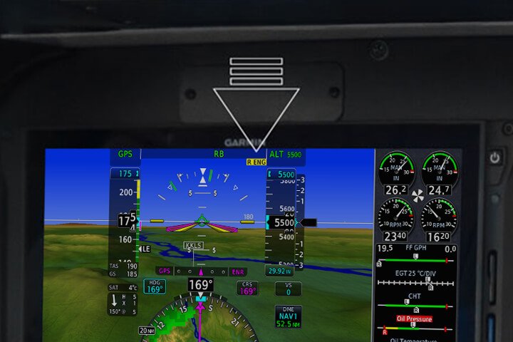
When the aircraft reaches the manufacturer’s published minimum control speed (VMC) during the takeoff roll, Smart Rudder Bias is automatically armed. Smart Rudder Bias continuously monitors engine parameters using Engine Indication System (EIS) data displayed on a G500 TXi or G600 TXi flight display and activates when the system detects a predetermined power differential between each engine. Once activated, rudder force is dynamically adjusted to aid a pilot in providing enough force to the rudder to help control a sideslip. A yellow annunciator for the associated inoperative engine is conveniently displayed along with autopilot annunciations on the G500 TXi or G600 TXi flight display, helping the pilot identify the issue quicker. Smart Rudder Bias can be deactivated via a panel-mounted switch.
Smart Rudder Bias enhances ESP settings for OEI condition
Garmin’s Electronic Stability and Protection (ESPTM) functions independently of the autopilot, working in the background to help pilots avoid inadvertent flight attitudes or bank angles and provides airspeed protection while the pilot is hand-flying the aircraft. Smart Rudder Bias applies enhanced ESP settings tailored to engine-out flight. Roll protection is modified to help correct for the roll tendency caused by the inoperative engine, while underspeed protection activates at a higher airspeed to help keep the aircraft away from the critical VMC speed and the associated loss of positive aircraft control.
PA-31 certified with GFC 600 – optional yaw trim also available
The GFC 600 is also now certified on select Piper PA-31 aircraft, and an automatic yaw trim option is available. Similar to pitch trim, yaw trim allows for manual rudder trim control with the press of a button, and automatic control of the rudder trim when the GFC 600 autopilot or yaw damper is engaged.
Smart Rudder Bias requires a G500 TXi or G600 TXi configured as a primary flight display (PFD) with EIS, which can be shown as a strip on the G500 TXi or G600 TXi, or on a separate TXi display. Additionally, a GFC 600 digital autopilot with the yaw axis option must be installed. Initial certified aircraft with Smart Rudder Bias capability include the Beechcraft Baron 58 and 58A, as well as the Piper PA-31-300, PA-31-310, PA-31-325, and PA-31-325CR. Additional certifications of Smart Rudder Bias will be forthcoming.
For additional information about Smart Rudder Bias and the Garmin Autonomi family of automated flight technologies, visit www.Garmin.com/SmartRudderBias.
The post Smart Rudder Bias: Safety-Enhancing Technology for Select Twin-Engine Piston Aircraft appeared first on Garmin Blog.
https://www.garmin.com/en-US/blog/aviation/smart-rudder-bias-safety-enhancing-technology-for-select-twin-engine-piston-aircraft/
Configuring Wake Modes to Maximize Battery Life in Cellular Asset Trackers
Operators want to use their expensive machines (loaders, sprayers, excavators, aircraft, etc.) as much as possible, because at the end of the day, business assets are more of an asset when they’re put to work. When a fleet is distributed over a large area, knowing where equipment is so it can be put to work can be a challenge.
Over the last decade, it has become common for larger or more expensive equipment to be delivered from the original equipment manufacturer (OEM) with a telematics standard. Sometimes it’s a simple position reporting modem, other times there’s a huge volume of operating detail being delivered to the cloud. In any event, it makes it much easier for operators to start tracking a fleet of assets when the equipment comes standard with tracking capability.
The challenge
There are still holes when trying to conduct an efficient operation with a full picture of the fleet. These holes exist because many fleets have equipment that did not come with factory telematics.
For example:
- Tenders, dump trucks, and other Milk Run equipment that create the maximum productivity of a working asset also typically do not have stock telematics
- Specialized equipment produced in lower volumes by smaller OEMs, and therefore not factory-equipped with tracking features
- Towed equipment that is not electrified (e.g. trailers, carts, screens, mowers, balers, tedders, rakes, grinders, chippers, etc.) and as a result have no built-in tracking connectivity
- Expensive attachments that are unpowered
- Older equipment that is in good working order but was delivered before connectivity was standard among major OEMs
Considering these holes, you may only be able to track a portion of the fleet. Even if it’s 75%, it’s not good enough. A project can’t happen if only 75% of the equipment is at the site. That makes these holes important to fill, but it also has to be easy. Operators don’t have the time or the interest to assemble a pile of dissimilar aftermarket technology offerings into a fleet tracking solution — they have a business to run.
The good news
In a previous blog (Understanding 4G LTE Categories) we discussed new kinds of cellular technology that have emerged as a portion of 4G offerings. These technologies, specifically NB-IoT and M1, create opportunities for very rugged and affordable “slap and track” cellular asset trackers. These kinds of trackers can be attached to any piece of equipment, and by using their own battery they can report its location for years.
![]()
This can be an easy fix to the problem, but getting real satisfaction out of these solutions is all about managing the battery life of the unit. Why?
- Many rugged asset trackers are made without replaceable batteries in order to achieve an IP67 or IP69K rating. Although these trackers are cheap, they need to be discarded when the battery is used up.
- Trackers with replaceable batteries lose the “easy fix” appeal once you’re spending time tracking down machines to charge their units or replace batteries. The appeal of this solution is ruined if you can’t leave a machine alone for at least a season — ideally for the life of the machine.
So, how do you use “slap and track” solutions to the maximum benefit of your business? I know people hate this answer, but it depends. As you consider your equipment tracking goals, it’s important to understand battery life and wake modes.
Understanding battery life in cellular asset trackers
Battery life is fixed, meaning you start with a bucket of energy and that is all you get. Therefore, to achieve maximum customer value, the focus needs to be about extending the duration of time that a rugged asset tracker can be used.
To maximize that energy:
- Devices need to be off as much as possible
- When on, devices should sparingly use the components that use a lot of energy (e.g. cellular and GPS)
Device manufacturers have put a bunch of battery management tools into these devices, and the asset tracking ecosystem, to make tracking as easy as possible. It varies by manufacturer, but when a device is advertised to have a 5-year lifetime, that’s typically based on an expectation of a few thousand positional reports over its lifetime. That works out to 1-2 position reports per day for five years. So, while the device’s lifetime is marketed in the form of years, in reality the lifetime is based on the number of positional reports utilized.
Understanding how different wake mode configurations affect battery life
Making the most of the battery management tools should get careful consideration as you deploy trackers. We recommend consulting with your tracking services or hardware supplier to dial this in as early as possible. Devices can typically be configured to report in the following ways (organized from most power hungry to least power hungry):
Periodic continuous reporting
For trackers that are integrated into the machine and connected to vehicle power, this is an easy and inexpensive thing to do. However, most customers with battery powered trackers will not want to use this mode. Having the device report every minute, or even every hour, will consume a lot of battery life.
Wake and report on movement
Many asset tracking devices include an accelerometer. These are great because they use minimal energy and can be used to wake the device when it moves. This is helpful if you want to know when equipment is moving from site to site or when equipment has begun working, for example. Depending on the tracker’s capabilities, it might be possible to set the device to report on movement but then to “snooze” for a period of time (e.g. 4 hours). A word of caution, however: if you can’t snooze its reporting behavior, this feature could run through the battery life quickly.
Wake and report on rest
This is related to the movement feature, but it notices when the device stops moving for a period of time (typically configurable) and then reports the device position. It’s an inverted version of the previous feature with the same benefits and challenges.
Start of day / end of day position reporting
This feature is generally easy to configure, easy to implement, and very friendly for battery life. Simply pick a time of day and have the unit report its position at that time every day. This can give you an overview as to where the equipment was left at the end of the day, giving you an opportunity to dispatch resources effectively at the start of the following workday. When combined cleverly with some of the above features (e.g. report equipment position at 5:00 PM, then report on movement in the event someone moves it after hours), it can be used to give an effective and timely overview of fleet positions while using minimal battery.
Wake on demand
This easy to use feature is very powerful and enabled by the newest generation of cellular technologies. For those of you who want to push your glasses a bit higher on your nose and nerd out with us about how this feature works, we’ll dig deeper in a future blog. For this post, we’ll talk about the capability at a high level so you can understand how to exploit it.
Using a computer or mobile device, you ask the equipment to report its location. This feature sends a message over the cellular network, which is stored in a mailbox of sorts. The device periodically checks that mailbox, using very limited energy, to see if it needs to report in. If there’s a request waiting, it reports its location.
The beauty of this feature is that whenever you need to know the location of an asset, you can have the device report in at the push of a button. The report doesn’t come back in seconds, because typically the device is configured to “check the mailbox” at scheduled intervals in order to minimize energy use. However, even waiting a few minutes to get the devices’ location is MUCH faster than driving from site to site looking for it.
Do you want future connectivity advice, insights, and information delivered to your door? Join our email list, and follow us on LinkedIn.
![]() David Batcheller – President & CBO
David Batcheller – President & CBO
![]()
https://www.appareo.com/2020/12/14/configuring-wake-modes-to-maximize-battery-life-in-cellular-asset-trackers/